THE GAS TURBINE AS A PRIME MOVER
FOR STANDBY POWER APPLICATIONS
Bernt Marcussen, Kongsberg Dresser Power A/S
P.O. Box 173
3601
Kongsberg,Norway
Introduction:
Many think that a gas turbine, as the
expression implies, solely burns gaseous fuels. This is not correct. It is true
that gaseous fuels of different qualities are excellent for a gas turbine;
however, the machine runs equally welt on liquid fuel.
Gas turbines on standby duty in most cases
operate on liquid fuel, either a light diesel fuel or kerosene.
Principle of operation:
Gas turbines are normally classified in two
groups, single shaft and two shaft engines. The compressor and turbine sections
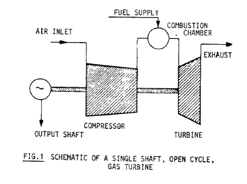
can be either of the axial or radial type. The principle of a single shaft gas
turbine is shown schematically in Figure 1. Air at atmospheric conditions is
drawn into the compressor and delivered from the compressor to the combustion
chamber at an elevated pressure. Fuel supplied to the engine supports the
continuous burning in the combustion chamber. The hot combustion gases pass
through the guide vanes to the turbine
wheel where energy is released from the hot
gases. The turbine wheel drives the compressor which is positioned on the
turbine wheel shaft (single shaft concept).
The net power which is the difference between
the power generated by the turbine wheel and the power absorbed by the compressor
is transmitted through a reduction gear to the output shaft where a generator
may be connected.
Single shaft gas turbines typically have very
high rotational speed stability. However, the torque transmitted is at its
maximum at rated speed and decreases rapidly with decreasing speed. Single
shaft turbines are therefore ideal in constant speed applications such as
generator drives.
In applications where operation over a wide speed
range is required a two shaft engine may be the best choice. A two shaft engine
consists of a gas generator section and a power turbine section. The gas
generator section is in principle the same as a single shaft turbine, where the
turbine wheel is designed to develop just enough power to drive the compressor.
The residual energy in the gas generator exhaust drives the power turbine
positioned on a separate shaft which is also the output shaft. With the dual
shaft concept, high torques may be transmitted at low speeds, making the dual
shaft gas turbine ideal for compressor drives, pump drives etc.
Figure 2 shows the principle of a dual shaft
gas turbine.
General features:
Weight and volume Gas turbines are much
lighter and much smaller than comparable diesel engines. The reason is that in
a gas turbine the compression, ignition and expansion are continuous processes
and in addition the rotating speed is considerably higher. The rotating
elements in a gas turbine are in complete balance and therefore only a High
engine frame structure is required. In the lower horsepower range the
difference in weight and size between the two
engine types is not very apparent, but in the higher range the difference is significant.
The low weight of a gas turbine and the fact that vibrations are almost non-existent
mean that the foundation requirements are minimal. The force transmitted to the
foundation is for all practical purposes equal to the static weight of the
machine and there are virtually no forces transmitted due to vibration. It is
fully acceptable to install a gas turbine generating set on a building floor
dimensioned for the static
weight of the set.
A
typical 1500 kW generating set has the following weights (KDP KG2):
Gas
turbine and gear
2.5
tons
Generator
5.0
tons
Common
base frame and auxiliary equipment
1.0
tons
Total
8.5
tons
Length:
approx. 4 meters (12 ft).
Cooling:
The cooling of a gas turbine engine is simple.
Only the heat generated in the rotor bearings and in the reduction gear needs
to be dissipated. This can easily be achieved in small oil to air cooler or oil
to water cooler, depending on the facilities available at the installation site.
It is customary to choose oil to air cooler
for a standby generating set, since experience has shown that the water supply is
often cut off at the same time a blackout occurs. The heat which needs to be dissipated
normally amounts to about 5% of the rated power of the generating set, which
calls for an oil cooler quite moderate in size. The ejector principal may be
applied to eliminate the need for motor driven fans. This increases the
potential for maintaining a high level of reliability. In a diesel engine the
heat to be dissipated is of the same order of magnitude as the rated power of
the engine. In a gas turbine the principal part of the heat loss is
concentrated in the exhaust gases, which leave the engine at a relatively high
temperature and at a high rate of flow.
Rotational speed stability:
Single shaft gas turbines have very high rotational
speed stability. This is the result of a large mass rotating at high speed.
Speed variations due to load changes are suppressed by the substantial amount
of kinetic energy stored in the rotating elements.
Fuel consumption:
The fuel consumption of small and medium size
gas turbines is normally about double the consumption of comparable diesel engines.
The fuel consumption may be reduced considerably through adopting recuperate for preheating which preheats the
air before it enters the combustion chamber. However, this is expensive and increases
the installation cost significantly. Standby generators would normally accumulate
very few hours of operation and the fuel consumption is of minor importance.
Noise:
Because of its cousin the jet engine, gas turbine
engines have a quite adverse reputation for being potential noise generators.
The design philosophy of aircraft jet engines is entirely different and there
is a very significant difference in the sound pressure levels of the two engine
types. This is not to say that the gas turbine engine needs no silencing - some
is required for all types of rotating power machinery. The noise emitted from a
gas turbine is air borne and at high frequency, and the silencing is therefore quite
simple.
Start-up time:
Start-up of a gas turbine implies that the heavy
rotor mass must be accelerated to a high speed level. A gas turbine would therefore
normally require a longer starting time than a comparable diesel engine. On the
other hand a gas turbine may be loaded to 100% immediately upon reaching rated
speed, while diesel engines often require loading in steps. Experience shows that
a start-up time of 40-50 seconds is fully acceptable for large standby generating
sets provided full load can be accepted immediately, when the engine reaches
100% speed.
Controls and supervisory systems:
By-an-large gas turbines require the same supervisory
system and controls as other prime movers. Normally this implies alarm and
shutdown in case of excessive levels of rotating speed, lube oil temperature and
exhaust gas temperature. Whether the design engineer specifies alarm or shutdown
depends on the nature of the specific installation in question.
Emissions:
Gas turbines operate with an air/fuel ratio
high above the stoichiometric level. This secures an almost complete combustion
and results in an invisible exhaust containing very small quantities of undesirable
components. Figure shows an exhaust gas analysis of a Kongsberg Dresser Power
KG2 gas turbine operating at approx. 1500 kW.

The extremely low content of CO is a result
of the high air/fuel ratio (approx.4:1) while the very low NOx-numbers is the result
of a combustion at low pressure and rapid cool-down of the flame front.
Lube oil system:
We mentioned earlier that a gas turbine generating
set requires a supply of lube oil to the rotor bearings and to the reduction
gear. Common mineral oils are normally specified however synthetic oils are
equally suitable. In the Kongsberg Dresser Power KG2 turbine the two rotor
bearings of hydrodynamic type are both positioned in the cold section of the
machine. This means that the oil cannot be contaminated by the exhaust gas, nor
will there be any loss of oil to the combustion chamber. The consumption of
lubricating oil in the KG2 gas turbine is therefore very small.
Auxiliary power requirement:
While on standby a gas turbine generating set
has some need for the supply of auxiliary power. For a KG2 generating set in
the 1300-1700 kW power range the power demand is limited to the following:
Charger for control system batteries (24V) :
2 kW
Charger for start batteries (48V) : 7 kW
Lube oil reservoir heater : 2 kW
Heater inside generating casing : 0.4 kW
Reliability:
The starting and operating reliability is probably
the most important feature required in a standby generating set. The single
shaft gas turbine with a single stage radial compressor and a single stage radial
inflow turbine is probably the simplest prime mover in existence today and it
has the potential for being the most reliable. The single shaft gas turbine is
in principle identical to a turbocharger except that the gas turbine has its
own combustion section and an output shaft.
Applications of the gas turbine:
In principle gas turbines may be installed wherever
there is a need for standby power, except in cases where an extremely short
start-up time is essential. Experience shows that gas turbines are more
competitive in applications above 1000 kW than in the lower power range. This
has to do with the pricing structure. The price of gas turbines per kW
increases with decreasing engine size, while it is the opposite for diesel
engines. The explanation lies in the difference in production volume for the
respective prime movers. The larger the power requirement, the more competitive
the gas turbine, particularly when the low installation and maintenance costs
are taken into consideration. Gas turbines often represent the only alternative,
particularly in cases where standby generating sets are engineered into existing
facilities and where it is difficult to supply the necessary amount of cooling
air for a diesel engine. For roof top installations the gas turbine is often
the only realistic alternative.
No comments:
Post a Comment